Heskheath Ltd | home
Hardwood log unscrambler | Conveyor pulley standard | Effluent channel screens | Chipper casing design | Log chain design
Conveyor pulley standard
Background
The traditional conveyor pulley typically has a through shaft on bearings supporting a lagged drum. The drum is attached to the shaft by means of taper lock units (or possibly welded in first generation designs), and each shaft has the bearings landings machined to suite the plant application. The drums may be crowned depending on whether they are to be used as head, tail or take up pulleys.
Despite having many weaknesses, this traditional design has, until recently, survived unchallenged.
The stub shaft concept
A taper locked through shaft is very functional provided the through shaft is suitably sized to withstand the cyclic bending load. The shaft deflection at the point of attachment must be within the specification of the taper lock supplier. If the deflection angle is exceeded, the mating surfaces of the taper lock break contact, and the drum can turn on the shaft, with severe consequences. To prevent this eventuality a larger, more costly, heavy shaft and taper lock are used on the pulley. (A similar argument holds true for welded assemblies)
At this point is worth noting that the pulley drum is in itself a structural member, with bending moments far greater than that of a traditional through shaft.
If the pipe can be used to drive the belt as well as carry the bending and drive torque loads, the through shaft can be discarded, eliminating the expensive taper lock units, the shaft material, and labour whilst reducing the overall mass of the pulley.
The ideal scenario would be one of a structural drum, with stub shafts to accommodate the bearings and drive mechanism (in the case of a drive pulley).
This assembly is quite possible and has been implemented with great success.
The stub assembly enjoys a number of advantages over a traditional pulley.
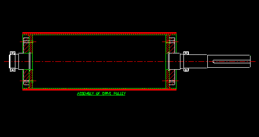
Drum standardisation
Generally speaking on any plant, there is a small range of conveyor drum diameters and lengths compared to the numerous variations in carrier bearing and drive designs. With the stubs now easily attached or separated from the drum, it makes sense to store the pulleys disassembled, in this way only one (possibly two) drums of each diameter and length are required on stock.
At this point the issue of crowned pulleys should be raised. If all pulleys were supplied uncrowned, the drum stock could be halved. In the face of this possible saving it should be asked, what benefit does crowning actually offer ?
Crowning of tail pulleys originated as a result of the tracking success enjoyed with the crowning on high tension, flat drive belt pulleys. Drive belts, owing to their high tension, seldom have carrier or idler rollers, hence there are very few factors that influence the tracking of a drive belt. A conveyor belt's tracking, particularly on the return side, take up, or tail pulley, is influenced by the type, condition, alignment and spacing of the return rollers, the belt tension, the alignment of the belt splices and possibly a plough scraper, to name but a few. Amidst all these variables the influence of a pulley crown will be negligible. It is however in the salesman's interest to sell crowned pulley, because they cost more (additional machining) and limit effective standardization.
With drums stored separately identification of spares is uncomplicated as the drum is described by diameter and length alone.
Stub identification
The storage issue presents a challenge, as it is never easy to recognize the subtle differences on the stub shafts, and it is likely that they, like the through shafts, will be incorrectly identified.
This problem is averted by putting "blank" or unfinished stubs on stock. For a specific pulley diameter, the stub has a corresponding attachment plate. The blank stubs have the attachment configuration completely machined, but the bearing landing surfaces are totally uncut. It is common to put a drive stub and a non drive stub on stock for each diameter of pulley. The blank portion of each stub has sufficient "green" to allow the stubs to be machined to suit any plant position using the specified drum diameter. This system now allows one to vastly reduce the number stubs kept on stock, and in addition the stubs are easily identified by the attachment plate size.
The stubs require approximately an hours machining each before the pulley is available for installation. In general this delay is acceptable as a traditional pulley failure would necessitate a complete pulley replacement while the stub design allows for positional repairs. Should it be absolutely necessary to put critical finished stubs on stock, they should be kept to a minimum.

Positional plant pulley repairs
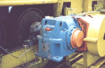
Should a stub be damaged in operation due to a bearing failure, for example, a replacement stub can be machined, and installed in position. This eliminates a complete pulley replacement, saving time and money. Similarly, should a shaft mounted gearbox require replacement and the gearbox seize onto the stub, a complete new stub with gearbox can be installed, and the failed unit stripped off for repairs without incurring significant downtime.
Stub refurbishment
A damaged stub is reconditionable with a minimum of effort and waste, due to the shrink fit assembly of the stub and attachment plate. The damaged portion is pressed out, and a standard blank shaft machined, pressed into the attachment plate, and return to stores. Not only does this reduce material costs compared to the traditional through shaft, but also reduces artisan machine time.
Lagging specification
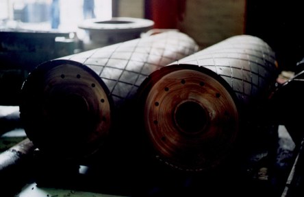
As the drum shell is now structural, corrosion or wear will impact on the design integrity, for this reason all pulleys are lagged. The lagging specification employed is a seamless cast polyurethane, with improved endurance properties. It is imperative to achieve a seamless, well bonded lagging, if the lagging is to ultimately fail through wear alone.
This lagging, if worn through, can be machined back and recast as new, this reduces material wastage, but this means that positional lagging replacements will no longer possible.
Engineering design
The stub pulley design is not conventional, and the attachment mechanism may generate skepticism, however the design is based on the simplest of engineering principles, a shrink fit, and a bolt assembly. With the stub machined to the correct interference fit, and the bolts correctly torqued, there is no opportunity for adverse influence.
To compliment the design, it is worth mentioning that this is not a theoretical concept, but a proven success.
Pulleys can be designed on a one off basis, but the full benefits of the design lie in the opportunity to standardise, and is hence best applied mill wide.
We look forward to being of help.
Standardisation example.
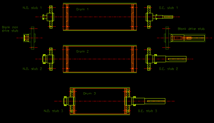
Refer to the above figure:
Drum 1 and drum 2 are identical in diameter, face length, and end plate attachment system. This standardisation is possible despite the fact that the drums may be used with shaft applications of different bearing sizes and bearing centres.
The stubs ND 1,2,3 and DE 1,2,3 have identical attachment plate configurations, and are machined from the ND blank and DE blank stubs respectively.
Ideally only blank stubs are kept on stock, but critical finished or semi-finished stubs may be added as the client sees fit. The blank, whether drive or non-drive will have sufficient green to allow final machining, to all sizes found on the client's site, used in conjunction with the specific pulley diameter.
Drum 3 is of the same diameter as the above two pulleys but has a shorter face length. It will however have identical end plate configuration and use the identical stub types.
The critical parameters of the stub attachment and interference fits are calculated from the most severe operating conditions (per drum diameter) identified on the client's site.
Hence with an established standard, provided the applications use equivalent diameter drums, one only need select the correct drum length, and the respective blank stubs (ND+DE or ND+ND), finish the bearing landings and assemble.